Truck Heater Electrical Fault Diagnosis
The heat in my 2000 Nissan Frontier blows both fuses when the heat is turned up to its highest setting. Given as it’s winter in Montana, fixing this seemed even more appealing to me than it usually would. While the wiring diagrams in this post are specific to my vehicle, this process can be applied to any vehicle.
Defining the Problem
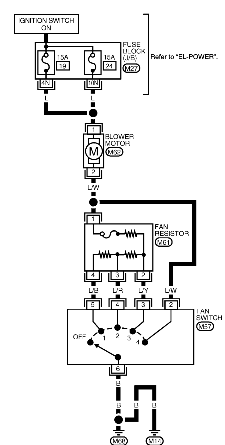
The heat in the truck goes out due to an excess number of amps that flow through the two 15 amp blower motor fuses. This happens only at the highest setting (fan switch #4) and happens every time, meaning that if this is a short, it is not an intermittent one. Both fuses are replaced each time, so this is not an issue of one fuse continuing to blow because its load-sharing counterpart is not available. To diagnose this much further, we will need access to the wiring diagrams for the heater circuit.

A common problem in these trucks is the blower motor resistor. These resistor boards have multiple different paths that operate the motor at different speeds as some allow more power to flow to the motor than others. These fail regularly and result in a short circuit that blows the blower motor fuses. However, we can immediately rule this out as the wiring diagram indicates that the highest level switch bypasses the resistor entirely. This leaves only a couple more methods of failure to investigate. The switch could have a bad ground, the blower motor itself could be faulty, or the wiring for the #4 switch could be exposed and shorting out.
Testing
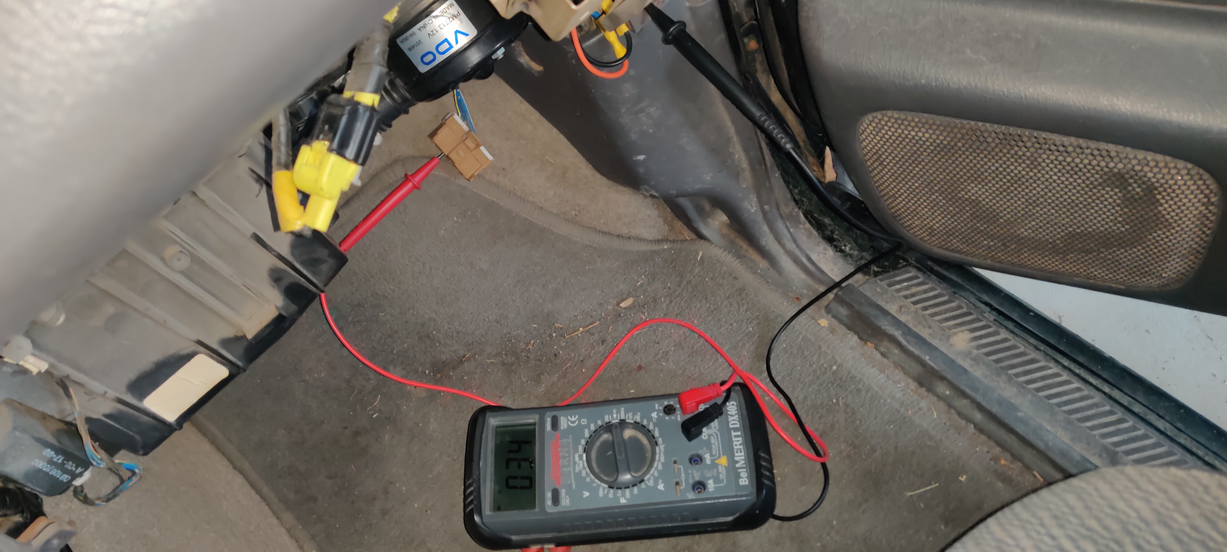
The switch itself is simple to test using a multimeter. To access the switch outputs, I removed the glovebox, and disconnected the connector from the resistor board. I used the above schematic to identify the connector wires with their corresponding switch.
I plugged one probe of the multimeter into the port corresponding to the switch state I wanted to test and grounded the other probe to the truck chassis. If the switch is operating correctly, the multimeter will read 0L when the wire is not selected by the switch. When it is selected, there should be a continuity reading from the multimeter. Below is a picture of the testing setup.

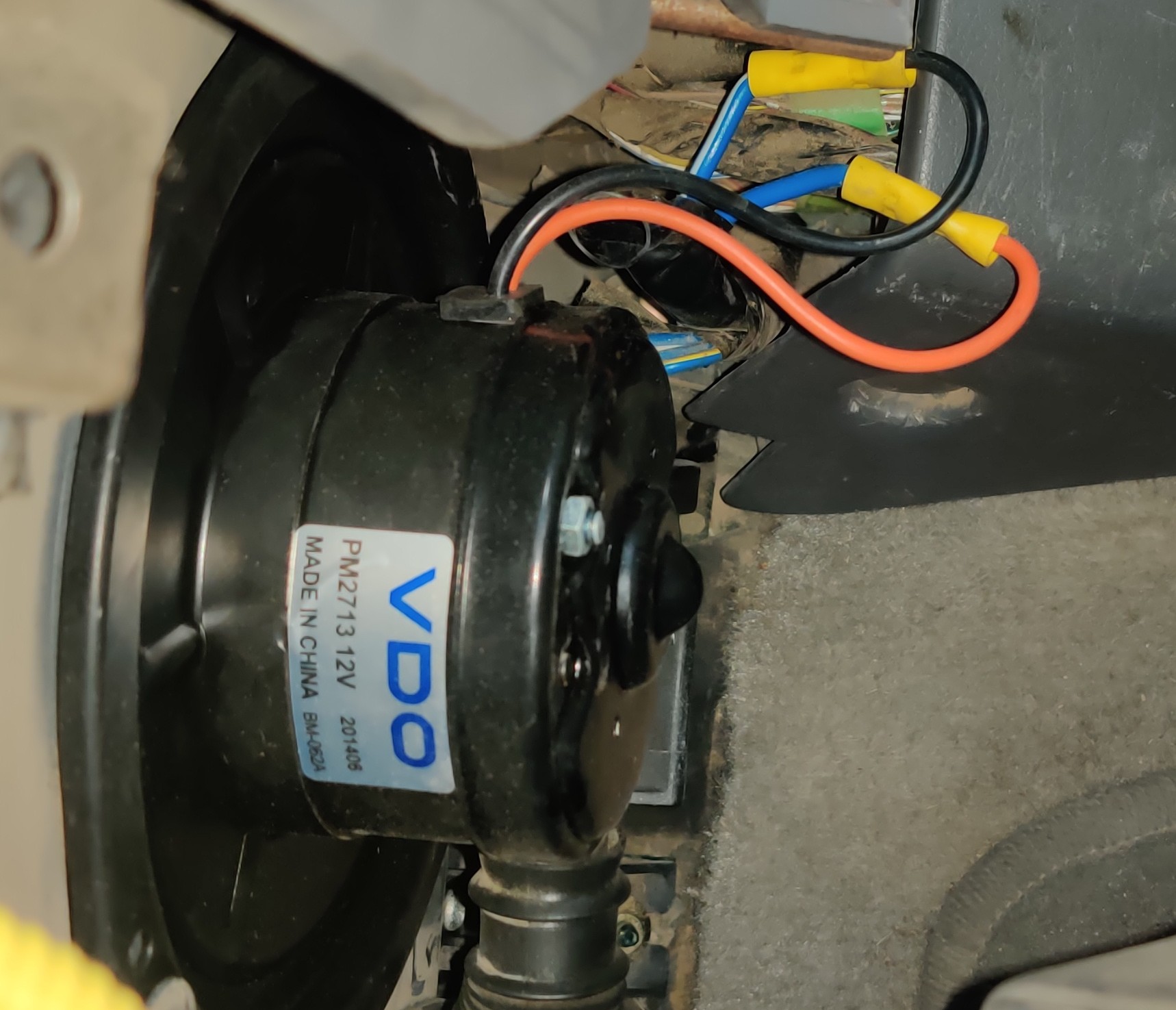
All the switches operated as expected, leaving only two likely cuprits for the problem. One of these quickly became far more suspect than the other. When I removed the glovebox to reveal the blower motor, it was apparent it was not an OEM part. The previous technician had actually cut the connector for the blower motor out entirely and crimped the positive and negative wires to the cheap motor they installed.

Solution
Inspection of the #4 switch wiring did not reveal any short to ground so I invested in a OEM blower motor to replace the old one. The motor arrived with no positive and negative terminal markings. However, it did have an arrow for the direction of spin, so I used multimeter attached to the terminals to determine the polarity by spinning the motor. I spliced the wires with Wago type connectors and made the blower motor terminal connections with spade connectors. The new motor no longer blew any fuses.